Material Characteristics of Lime Plaster in Goguryeo Mural Tombs (I): Focusing on Lime Plaster Excavated from Anak Tomb No.3
Article information
Abstract
Physical and chemical investigations were conducted on lime sample from Anak Tomb No.3 to determine the properties of the plaster material. The morphological and physical characteristics of the specimens were analyzed using both a microscope and a polarizing microscope. The constituent materials were identified through X-ray diffraction and scanning electron microscope-energy dispersive spectrometer, and the qualities of the mixed material were established through thermal analysis. Additionally, micro-computed tomography was used to non-destructively confirm the internal structure and density characteristics. The lime sample was recognized as a lime plaster material with two unique layers. Each layer shows variations in material properties. It is speculated that this lime specimen was used to finish the edges of the authentic wall within Anak Tomb No.3. Through the synthesis of various morphological attributes and physical properties; the whiteness, durability, thinness, and repetition of the layers, as well as smoothness of the lime plaster used for Anak Tomb No. 3 indicate that a high level of lime wall plastering technique was used in Goguryeo Tomb. It was possible to evaluate the refined level of lime wall manufacturing technology in the Goguryeo era.
1. INTRODUCTION
Conservation research on Goguryeo mural tombs started in 1989 when a UNESCO research team conducted a scientific investigation of the Deokheung-ri mural tomb and from 1998 to the early 2010s, Korea conducted research on mural painting techniques and pigment analysis. Interest in the preservation of the Goguryeo tomb paintings increased significantly after they were declared a UNESCO World Heritage Site in 2004, and both domestic and international experts have been actively conducting research to further this endeavor. In 2006, a joint conservation survey involving North and South Korea was conducted to assess the preservation status of the 10 Goguryeo mural tombs in the Pyongyang area (National Research Institute of Cultural Heritage and South-North Exchanges and Cooperation Support Association, 2006). During this effort, detailed investigations and research on the murals in Jinpari Tomb No.1 and No.4 were carried out (National Research Institute of Cultural Heritage and South-North Exchanges and Cooperation Support Association, 2007). In the early and mid-2000s, scholarly research primarily focused on the analysis of pigment components found in mural paintings (Ahn, 2003; Yu, 2005). Later, from the late 2000s to the early 2010s, various studies were conducted on the production techniques and material properties of lime walls. These studies included reproducing limestone layers of Goguryeo mural tombs to conduct technique research (Lee and Han, 2006), analyzing lime wall material properties (Lim, 2009), and studying lime mural production techniques (Lee et al., 2013). However, research on Goguryeo mural tombs has not made significant progress since mid-2010, mainly due to political reasons between North and South Korea, as well as limited accessibility. This study performed a thorough physical and chemical analysis of lime specimens from Anak Tomb No.3. These specimens have not been previously investigated by North and South Korea teams. The focus of the study was the examination of the lime utilized in the finishing of the walls of the Goguryeo tomb murals. The primary objective was to explore the material properties and manufacturing technology.
2. RESEARCH SUBJECTS AND METHODS
2.1. Research subjects
Anak Tomb No.3, situated in Oguk-ri, Anak County, South Hwanghae Province, is a mural sepulcher that bears an explicit monumental inscription indicative of its construction date as the year 357. The monument underwent excavations conducted by North Korean researchers in both 1949 and 1957. The tomb structure comprises multiple chambers, including the main chamber, a chamber, an antechamber, left- and right-side chambers, additional chambers, and a corridor. Each chamber is constructed using an erect polished plate. The mural was directly painted onto the stone wall. The spaces between the walls and the ceiling stones, as well as the corners between the stone walls, were filled with white ash as finishing (National Research Institute of Cultural Heritage, 2019).
The plaster sample found atop the wall featuring the portrait of Anak Tomb No.3’s master is approximately 12 × 7 × 5 mm (Width × Depth × Heigh). One side of the specimen is smooth, implying that it is the final wall surface, while the other side is uneven in thickness and has soil impurities. The reverse side was observed and is supposed to have come off from within the wall (Figure 1).

The sample of Mural in Anak Tomb No.3 (A: Sample location, B: Front of sample, C : Back of sample).
2.2. Research method
A microscopic examination was performed to ascertain the specimen’s physical and morphological attributes. An optical microscope (HRX-01/RX-100, Hirox, JPN) was used to assess the layer, thickness, surface condition, color, constituent materials, mixing state, additives, and other components of the specimen at a magnification of 10 to 50 times. The plaster’s mineral and particle composition was examined using a polarizing microscope (DM2500, Leica, DEU). The specimen was mounted, turned into a thin section, and examined at magnifications ranging from 20 to 200 x. X-ray diffraction analysis (XRD, Empyrean, Malvern Panalytical, UK) was utilized to investigate the compounds and crystal structures of the materials in the plaster’s composition. The plaster was finely ground into a powder and subjected to analysis under the following conditions: 45 kV/40 mA, scanning from 5 to 60 degrees at 0.01-degree intervals for a duration of 200 seconds.
The microstructure of the plaster was observed using a scanning electron microscope (SEM, JSM-IT300LV, Jeol, JPN), secondary electron image (SEI), and backscattered electron image (BEI). Additionally, the main chemical components of the constituent materials were observed. An energy dispersive spectrometer (EDS) attached to an SEM was employed to confirm these observations. Analysis conditions entailed applying 20 kV and 74 μA for 60–200 seconds. The thermal properties and additives of the plaster constituent materials were determined through thermogravimetric/differential scanning calorimetry (TGA-DSC, Labsys Evo, Setaram, FRA). The analysis was conducted under N2 gas at 30–1000°C, with a heating rate of 10°C/min. Microtomography (Micro-CT, XT H225, Nicon, JPN) was used to investigate the internal structure, density, and pore state of the plaster specimen in a non-destructive manner with a maximum power of 225 kV and spot size taken at 3 μm intervals. Additionally, laser particle size analysis (Mastersizer 2000, Malvern instrument, GBR) was conducted to investigate the particle size and classification characteristics of the plaster.
3. RESEARCH FINDINGS
3.1. Microscopic examination
The front surface of sample appeared smoothly finished with an irregular yet consistent pattern, presumably a mark of application. Thin-concentration plaster was observed on the exterior with several layers, repeatedly applied. Notably, paint clumping occurred on the outside when applied over thin plaster. The plaster appears to be a mixture of white or off-white with black aggregates and fine granules throughout its surface and interior, likely composed of brown or reddish-brown soil (Figure 2).
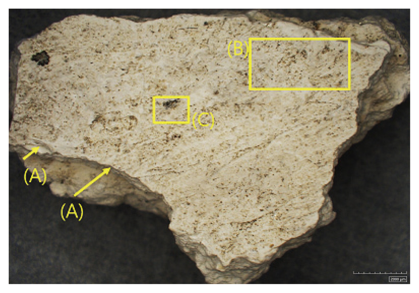
Condition of sample (A: Paintbrush marks, B: Mineral particles, C: Black aggregation).
When the plaster sample was mounted and analyzed under a microscope, two distinct layers were observed: an upper layer (ref erred to as Layer 1) with a thickness of approximately 1.6 mm and a lower layer (referred to as Layer 2) estimated to be 4.0 mm thick or more. As a result, the specimen was divided into these two layers, and their configuration was verified. Each layer exhibited variations in color, substrate composition, and distribution of substances. Upon inspection with the naked eye, Layer 1 appeared as a light off-white while Layer 2 was yellowish-white. The plaster includes particles of soil or cementing materials in different sizes and hues, as well as mineral particles like quartz and mica. Layer 1 is distributed in a relatively small proportion compared to Layer 2, which contains a larger amount of soil and minerals (Figure 3).
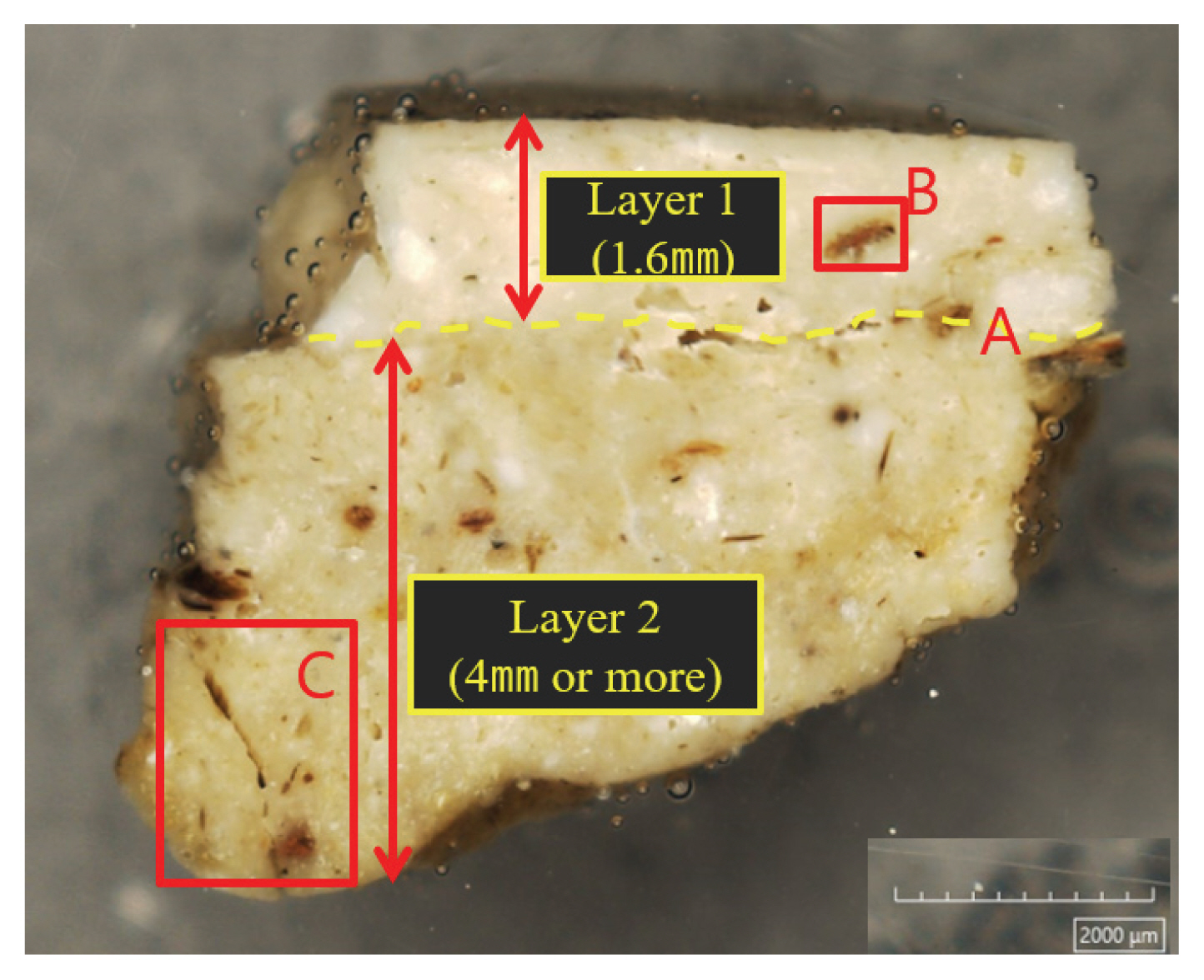
Cross-section of sample (A: Separation line between layers, B: Soil mixtures, C: Mineral mixtures).
3.2. Polarizing microscope research
The cluster’s underlying matrix was found to be a fine-grained calcareous material, without any observed polarimetric characteristics of calcite mineral. Layer 1 contained fewer quartz and mica minerals in comparison to Layer 2, and disordered amorphous colloids were present. Layer 2 is comprised primarily of fine-grained lime as the basal matrix. It was found to be a blend of minerals including quartz, biotite, and amorphous colloids with a size range of 100 to 500 μm (Figure 4).
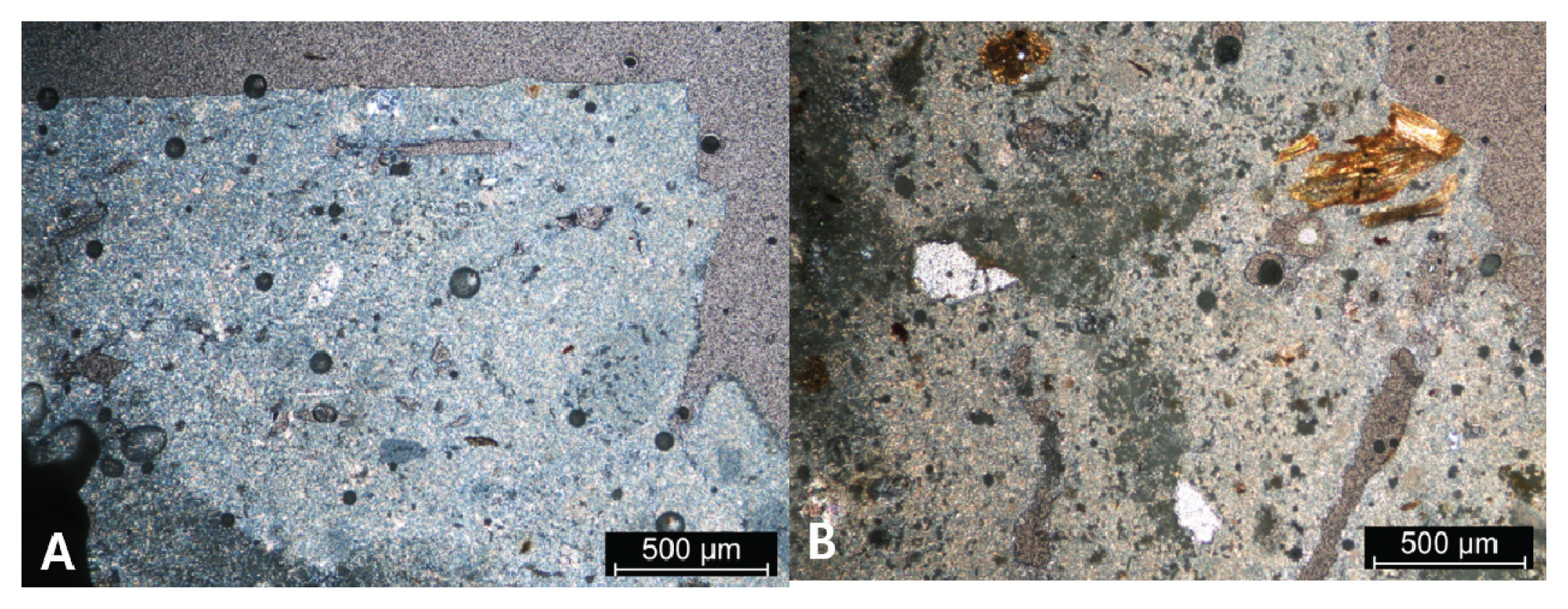
Images of cross-section using the polarizing light microscope (A: Detail of layer 1, B: Detail of layer 2).
3.3. Crystal phase analysis (XRD)
The primary mineral component of the plaster was recognized as calcite. However, quartz was detected together with calcite in Layer 1, while in Layer 2, quartz and biotite, as minor minerals, were discovered alongside calcite (Figure 5).
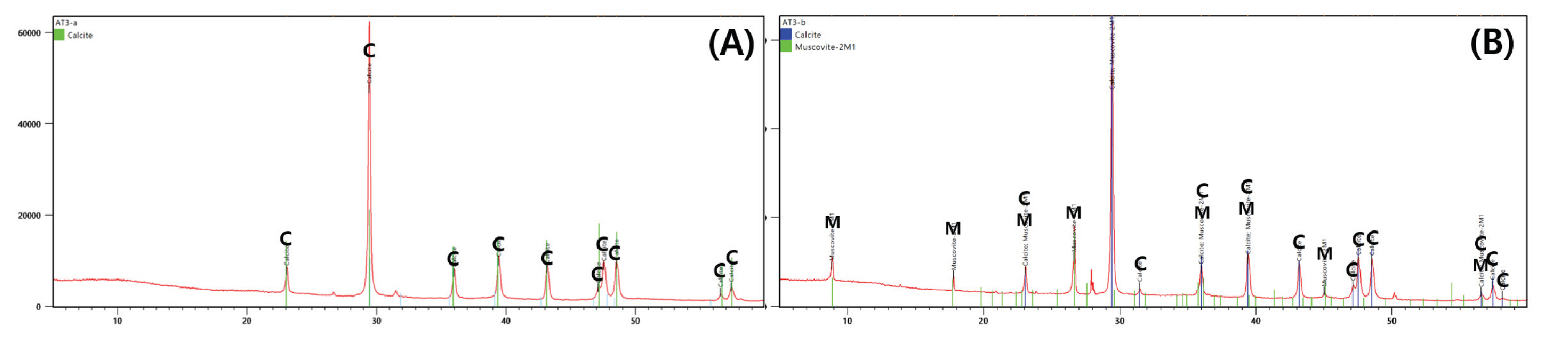
X-ray diffraction pattern of sample (A: Layer 1, B: Layer 2)(C: Calcite, M: Muscovite)
3.4. Microstructure and chemical composition analysis (SEM-EDS)
To examine the microstructure of lime plaster, a portion of the specimen was collected and observed under a SEM. At a magnification of 500 to 1,000 times, the sample revealed primarily granular or irregular lime particles (Figure 6). An EDS analysis was conducted on each layer of the cross-sectional specimen. Layer 1 exhibited the main detected elements of Ca, Si, Al, Cl, Mg, and Fe, while Layer 2 exhibited the main detected elements of Ca, Si, Al, Cl, Fe, and Mg (Table 1). Based on the particle analysis of the plaster in Layer 2 observed under an electron microscope, only four elements (Mg, Ca, C, and O) were detected, and they were identified as dolomite crystals (Figure 7).

SEM image of bulk sample (A: Atypical crystal, × 500, B: Atypical crystal, × 1,000).

Chemical composition for Layers of sample
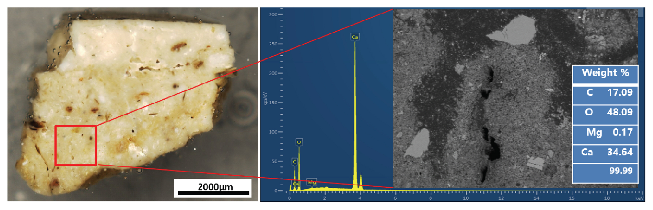
EDS spectrum and chemical composition of dolomite particle in layer 2.
3.5. Thermogravimetric-differential scanning calorimetry (TGA-DSC)
After conducting a thermal analysis of Layer 1, an endothermic reaction was detected at a temperature range of 750–860°C and an associated weight loss rate of approximately 41.72%. This is comparable to the weight loss rate manifested by calcium carbonate, which is around 44%. Based on the temperature range, it was determined that the material is comprised solely of lime. An exothermic reaction took place at approximately 300°C in Layer 2, followed by a weight increase. Another exothermic reaction occurred at around 420°C, followed by an endothermic reaction in the range of 680–800°C. The weight loss rate due to the decarboxylation reaction was approximately 28.97%. Considering the additional two weight losses, it is speculated that complex materials were present in the mixture (Figure 8).
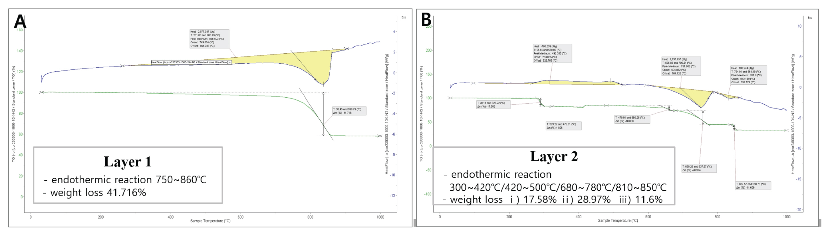
Thermal analysis results of using the TGA-DSC (A: Layer 1, B: Layer 2).
3.6. Micro-computed tomography
The specimen has a total volume of 415.36 mm3, with a pore volume of 22.38 mm3 translating to a porosity of 5.11%. In reviewing the Micro-Computed Tomography (Micro-CT) images for each slice, it was found that Layer 1 has a greater variety of bright white areas compared to Layer 2, indicating a higher density. More voids were observed in the region of Layer 2 (Figure 9). To numerically compare the density differences within layers, a digital image analysis program (Picman, US) was utilized to quantify and compare grayscale color information from the image. The distinct RGB (Red, Green, Blue) color values that differentiate colors were categorized into five levels, and the pixel count for each RGB level was calculated to determine the ratio of each pixel to the total. The images were obtained from the region that corresponds to Layers 1 and 2 of the CT image. The average color information value was calculated and compared for each image. The mean intensity of Layer 1 was 1 35.67, whereas that of Layer 2 was 107.77.
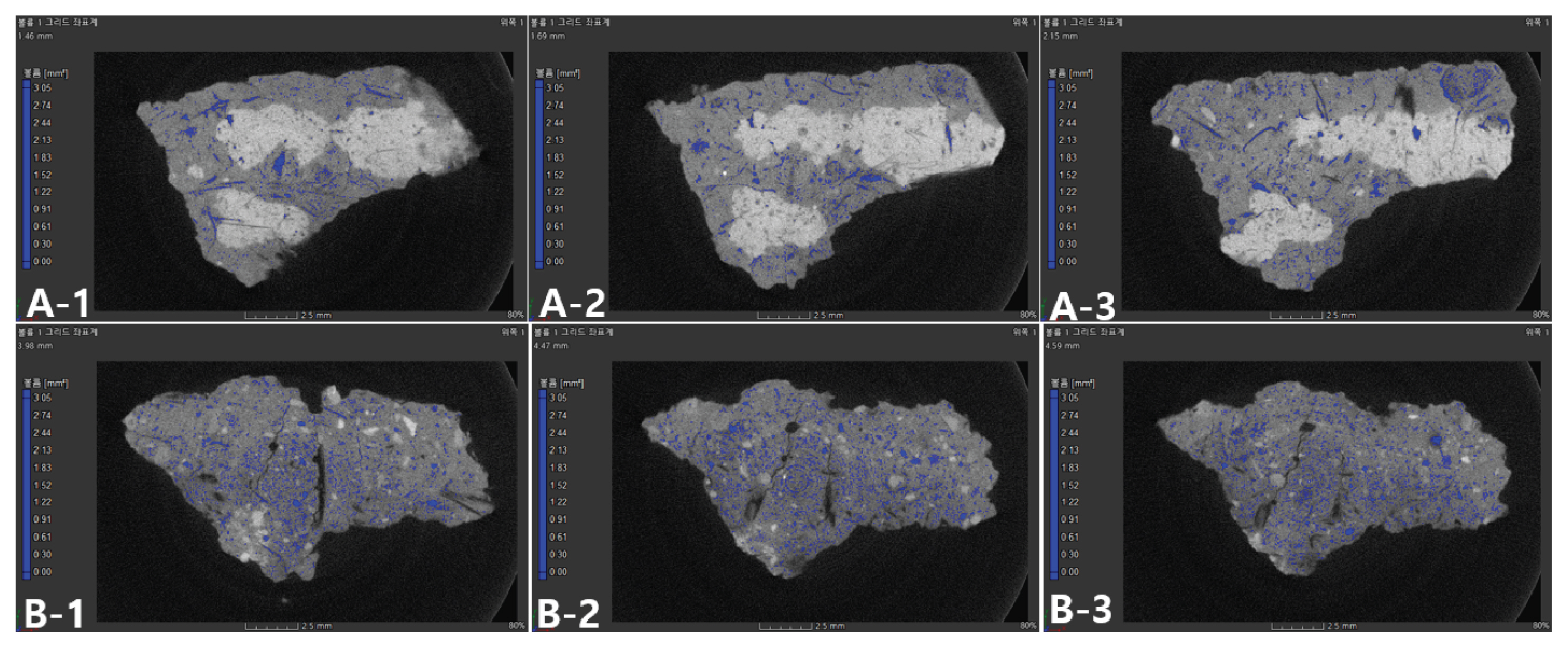
Analysis of Micro-CT images for layers (A-1~3: Layer 1, B-1~3: Layer 2).
3.7. Laser particle size analysis
After submerging the entire sample in distilled water and utilizing ultrasound to determine the naturally dissociated particles, it was discovered that the particle size predominantly fell within the silty (2–50 μm) and clay (0–2 μm) ranges. The distribution was 54.07% for silt, 31.55% for clay, and 14.38% for particles with a diameter of 50 μm or greater. The particle size range was 0.31–251.78 μm (Figure 10).
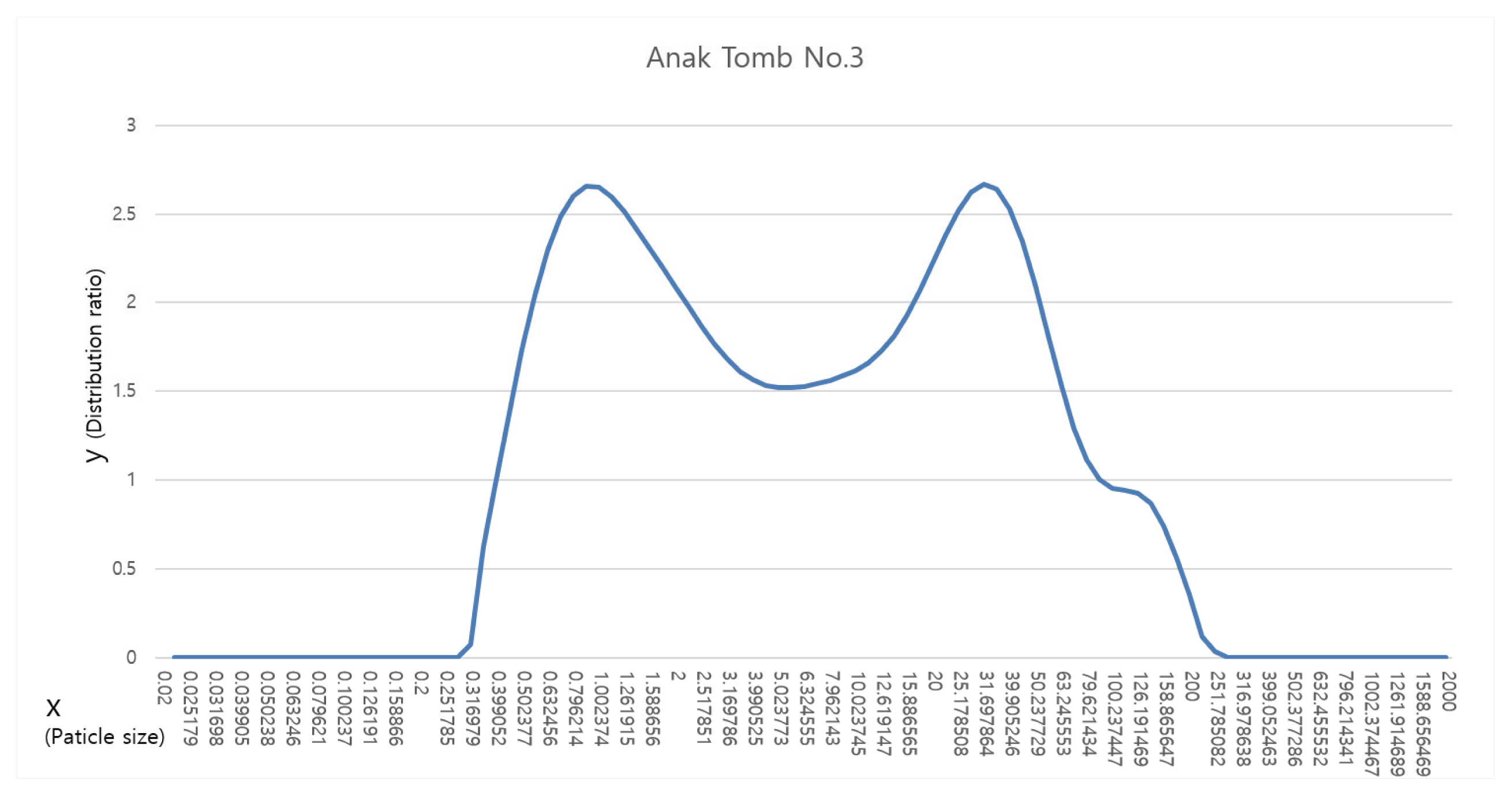
Results of laser particle size analysis of sample.
4. DISCUSSION
This study conducted a scientific analysis of the lime plaster sample collected from Anak Tomb No.3 to examine its material properties and thereby determine the technique used to produce the wall.
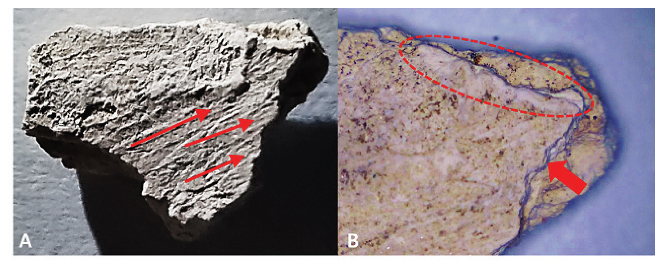
While the sample was small in size, its thickness suggested that it was presumably part of the wall. The sample had a smooth surface, which showed some traces of applications and layering. The mural painting in Anak Tomb No. 3 utilized a stone surface mural production style, wherein the artist drew directly on the surface of a rock without using lime plaster. For stone surface murals in Korea, lime plaster is often used for lines between stone materials. In the mural painting in Anak Tomb No.3, however, some parts were found to be painted on the surface of the rock, such as the upper part of the wall featuring the portrait of Anak Tomb No.3’s master, and not just between the stones. This shows that the plastering technique was used to produce the lime wall (Figure 11).

Lime plaster used to finish wall edges in Anak Tomb No.3.
A microscopic analysis revealed that the lime plaster was made up of two layers, with a thin upper layer of about 1.6 mm and some traces of the plaster repeatedly applied at a constant thickness. It is speculated that the finishing layer was made by applying plaster of a somewhat watery consistency several times. Traces of this technique suggest that considerable know-how was available at that time regarding creating a robust wall layer for a mural in a tomb (Figure 12).
Finishing layer of lime plaster (A: Traces of repeated application of lime plaster, B: Traces of plastering several times using a thin consistency paste).
To discern differences between the two layers as regards the material properties of plaster, this study compared the results of the analysis of the upper and lower layers and found that the two layers had some differences in their physical states and material properties. Layer 1 was very thin; it included calcite as its primary mineral component as well as some quartz. Additionally, it contained fewer impurities and soil colloids than Layer 2 and was characterized by lighter color and higher density. A thermal analysis of Layer 1 also confirmed that it mostly consisted of pure calcite. Further, an EDS analysis based on the electron microscope showed that Layer 1 had a lower percentage of elements (Si, Al, and Fe) from the soil than did Layer 2. Although it was not possible to determine the total thickness of the wall to which Layer 2 belonged, Layer 2 was found to be thicker than Layer 1. Quartz and biotite, along with calcite, were detected in the crystal structure, and dolomite crystals were found in the microstructure. Using the polarizing microscope, this study observed that Layer 2 had a higher percentage of some other minerals, such as soil colloids, quartz, and biotite, within the plaster; moreover, a thermal analysis revealed the reactions and weight loss values, indicating that Layer 2 had a mixture of materials other than pure lime (Figure 13).

Comparison of lime plaster characteristics of smaple in Anak Tomb No.3
Since durability of a wall is generally weak if no soil mixture is used when the wall is produced, it is necessary to mix soil-based materials to achieve wall durability. Previous studies in Korea on lime walls for mural paintings in Goguryeo tombs have shown that mortar was made by mixing lime and soil to produce walls. An analysis showed that Hahaebang Tomb No. 31 was produced by using highly pure slaked lime to create the initial and finish layers of the wall and by adding clay or sand to the plaster depending on the layer (Ahn, 2003). Further, it was confirmed that lime, charcoal, and weathered clayey soil were mixed in the plaster used for Jinpari Tomb No. 4 (Lim, 2009). In the lime plaster from Anak Tomb No. 3, it was observed that the percentage of soil was extremely low, color of the plaster was very white, and highly pure lime was used. Therefore, it is highly likely that the soil materials were not intentionally mixed but included as impurities when kneading the plaster. Another possibility is that the plaster was mixed with white clay, such as kaolinite or halloysite.
This study used Micro-CT to determine the pores inside the layers and the layers’ density without destroying the sample. Accordingly, it found very few pores between the layers, and density of the upper layer was higher than that of the lower layer, which confirmed that the upper layer was plastered more densely. Moreover, traces of multiple applications on the sample’s surface and thinness of the upper layer imply that the lime plaster used to create the finish layer was kneaded into a somewhat watery consistency, which is a condition conducive to plastering. Results of these analyses suggest that the level of lime processing and plastering techniques used for the mural was quite high, even though the wall was made during the early days of Goguryeo.
5. CONCLUSIONS
In conclusion, this study observed the following material properties of the lime wall used for Anak Tomb No.3:
1. The lime plaster had two or more layers; the layers’ thickness ranged from approximately 1.6 to 4 mm; and there were differences in the layers’ physical properties, such as their color, mixture distribution, and density.
2. The primary mineral component of the lime plaster was calcite, and other minerals, such as quartz, mica, and feldspar, were detected in trace amounts, while some dolomite particles were observed in the lower layer. Most particles were fine particles.
3. Chemical analysis of the lime plaster detected Si, Al, and Mg, indicating that soil-based materials were mixed with the plaster. However, microscopic observations confirmed that very few presumed soil particles were mixed. Therefore, unlike the common production style found in the walls used for mural paintings in Goguryeo tombs—wherein soil-based materials were mixed with lime plaster—almost pure lime plaster was used for Anak Tomb No.3. Nevertheless, the soil components detected in this study suggest that some white soil materials, such as kaolinite, were mixed with the plaster.
4. Considering the pores found inside the lime plaster, density of the finish layer, and traces of applications on the surface of the sample, the lime plaster was prepared and used under conditions conducive to the production of a mural by accounting for the consistency of the plaster and its solidity when hardened. Therefore, the whiteness, durability, thinness, and repetition of the layers, as well as smoothness of the lime plaster used for Anak Tomb No. 3, indicate that a high level of lime wall plastering technique was used.